A site plan is a document that precisely maps out the area of the building site to scale. Generally speaking there are two site plans provided:
- Existing site plan – the ‘before’ shot. This site plan shows the site in its current state.
- Proposed site plan – the ‘after’ shot. The proposed site plan shows what’s going to change, and how the site will look once construction’s finished.
What’s on a site plan?
The basic idea behind a site plan is to show:
- the shape of the site
- the size of the site - shown using a scale
- the orientation (i.e. which way is north)
- the geographical location of the site
- the precise positions of things like trees or rocks
- any variations in height (shown as contour lines)
- the area that’s going to be covered by the house and any other structures you’re planning on putting up
- any easements, rights of carriage, driveways, existing stormwater drainage etc.
- the exact location and footprint of any existing structures
- any relevant features of the area surrounding your building site - particularly things which might affect access to the site or construction
[caption caption="The title block provides vital details about the plan on which it appears." align="right"]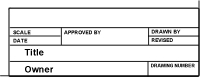
[/caption]
What is a 'title block'?
A site plan should also contain what’s called a ‘title block’. This bit of information appears on most types of plans, and normally sits in the bottom right hand corner of the page (or sometimes at the top right corner). The purpose of the title block is to show administrative details, including:
- the name and contact details of your designer, architect or builder
- the title or name of the drawing
- the drawing (or revision) number
- signatures, initials, dates etc.
What do all of those small symbols and figures mean?
While much of what’s on a site plan is pretty self explanatory and the important parts are usually clearly labelled, there’s an awful lot of fine detail provided that can easily slip past the untrained eye.
Everything down to the types and thicknesses of the lines, the directions of arrows, small abbreviations and the symbols and markings holds some significance, and will communicate specific information about the site.
Check our table of abbreviations and symbols for more information.
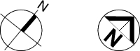 Figures like these tell you how the house is orientated.
Orientation and scale
All plans should feature a north point to show the orientation of the diagram – and where possible, it’s preferable for all of the diagrams being used (e.g. site plans, floor plans, drainage plans etc.) to be oriented in the same way to prevent any unnecessary confusion.
[caption caption="Graduated scales give an impression of distance and size." align="right"]![]()
[/caption]
Scale is normally represented on plans using a written ratio (e.g. Scale 1:100), as well as a block or granulated scale, which gives a graphical representation of sizes and distances as they’re shown.
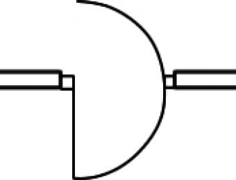
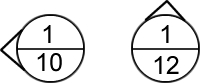 Callouts and cross references tell you where to find more detail about a particular part of a plan.
Callouts and cross references
The level of detail shown on a site plan will depend on what can reasonably be drawn in the scale of the drawing. Where extra detail is required – or a reference to show an aspect of the plan from another perspective is provided - it’s normally included using a cross-reference to a separate diagram.
There are quite a few different types of references that can be used, each of which indicates a different type of detail or drawing. The top number typically identifies the drawing / detail / sequence number of the diagram, and the bottom number indicates the sheet number on which it appears.
- What's the difference between an architect and a building designer?
- How to consult with an architect or building designer
- How to choose an architect
- How to read house plans & diagrams
 How to read site plans
- How to read floor plans
- Elevations, framing plans, wall sections, and shadow diagrams
- Floor plan abbreviations and symbols
- Should I renovate or demolish?